Electronics were a must for me. Probably the best thing I liked about keeping the birds in the chicken tractor was not having to open and shut a coop door each day. Therefore an automated coop door was a requirement for this build.
 When I started the electronics, it became a “give a mouse a cookie” event. Automated door meant battery, battery meant solar panel, and since we have a solar panel, let’s do lights. And for grins, I’m toying with adding a winch to raise and lower the aviary, so let’s add something for that.
I already had the battery, lights, and timer from the A-Frame build. However I wanted to add solar to charge the battery instead of manually charging it 1-2 times a week. I looked at some kits online and chose a cheep 20W panel and charger off Amazon. The door automation took more thought.
I looked online and saw people using car antenna motors to open and shut the door. I like this idea. It would limited the amount of push pressure when shutting the door, which would prevent birds from getting caught, but this could also end up leaving the door open if the door got in a slight bind. The biggest con for me not to use this was that, for my build, constant power would need to be applied when the antenna was extended, which would be during the nighttime when the door was pushed closed. This would cause a draw on the battery; however, it would be a slight draw because it’s not running the motor.
Liner actuators are the other main way I see coop doors automated. These are on when moving, then switch off once extended or retracted. To reverse the direction, you reverse the polarity. So they only draw power twice a day when opening or closing. They also have a lot more push/pull torque. This would prevent the door staying open at night because of a slight bind in the door; however, poses a danger if a chicken is in the way. I was leaning toward the linear actuator when once again my father-in-law helped out and gave me one he had.
The actuator requires a DPDT relay to reverse the polarity. In the end, the power draw from the power antenna was probably a wash with the relay draw; however, the way I architected my door, the relay draws power during the day and the antenna would be drawing at night. Theoretically there should be less draw on the battery as the solar panel will power the relay during the day. Again, the draw is slight and probably not worth worrying about, but I do.
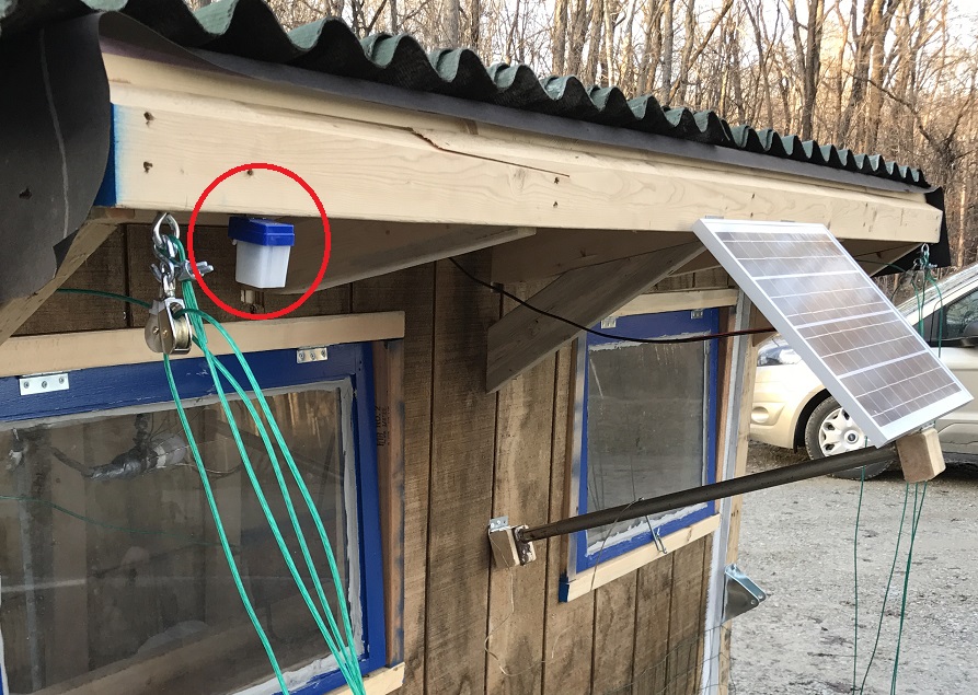
 I’ll still have a constant phantom power draw from the photocell (circled in red in the picture of the solar panel) that’s used to trigger the door at morning and night, but that’s used for either method. I like the photocell because it changes with the season and will be more consistent with morning and night than trying to use a timer.
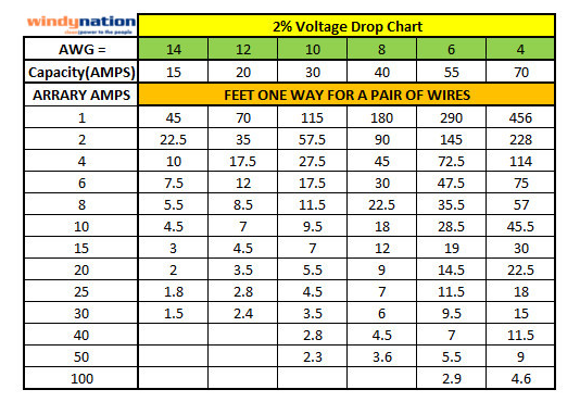
I spent some time to determine the correct wire for the distance. Based on this chart, the battery distance of 12′ with 5A puts me at 12 gauge. I decided to use 12 AWG to the battery and 16 AWG to everything else to achieve a 2% voltage loss. I save old appliance cords that are long, like from vacuum cleaners, and used these for the rest of the connections. They are 16/17 gauge and should keep me in the 2% drop range based on a combination between the previous chart and this chart. As with the power draw of the antenna, I may be over thinking/engineering this for a chicken coop.
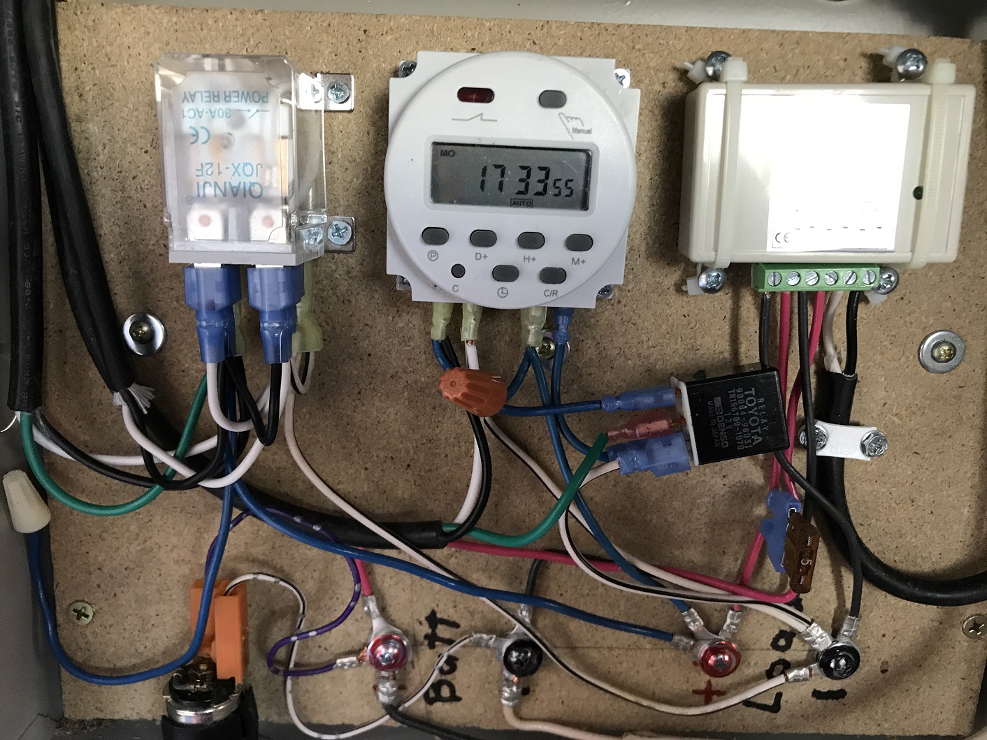
Finally, I had picked up an old electrical panel box somewhere and I used it to house all brains of the electronics. I added a board to help me mount everything in the box. Here’s how it fits together.
 Battery
First I bring the battery wires into the box to a couple of terminals. This allows me to connect things directly to the battery and bypass the solar charger, which is rated for 3A. My first add-on is a cigarette lighter that I mounted in the bottom of the box.
Solar
Then I attached the solar charge controller to the battery terminals. The Solar panel connects into the charge controller. Finally I take the load from the charge controller to two more terminals that I’ll connect everything else to. Connecting solar is pretty simple using a charge controller, especially compared to the wiring for the lights and door.
Lights
As I mentioned in my previous post on the lights, I need a relay for the timer to power the lights. I could not power my light directly through the light switch. I also used 3 wires going to the light so I could add a flip switch to override the timer and turn the lights on. These two items make the wire diagram look like spaghetti, but hopefully you can follow it.
**If you’re comparing the diagram to the photograph, the diagram has positive in red and negative in black. That does not correspond to the wires I actually used so I list the color of the wire in the photograph in (parentheses).
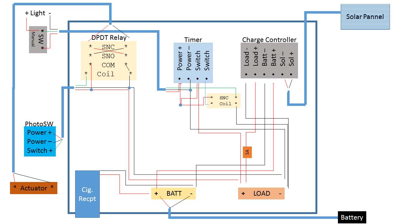 Power(positive) comes from the load terminal to the switch side of the timer, a jumper wire goes to a wire nut that ties to the run side of the timer, which also jumpers with the power(black) wire to the light, and the switch side of the relay. All these connections have power full time. The other side of the relay switch goes to the switched wire(green) to the light. And the other switch side of the timer connects to the coil side of the relay.
Negative goes from the load terminal to the relay coil and run side of the timer, where it’s jumpered with the negative(white) wire to the light. This provides the 3 wires going to the light as Black=always on positive, Green=switched power from the timer, white=negative(common). Because I’m using wire commonly used for AC, I switched to AC Black/white color standards when I attached the wire or when I ran out of Red/black wire. It makes sense to me since I’ve dealt with both.
At the light switch, negative(white) goes straight to the light. Positive(Black) goes to one side of the switch. Switched(green) goes to the other side along with a jumper wire to the positive side of the light. So if the light switch is on, it provides power to the green side that’s jumpered to the light and the light comes on. Turned off and the light is off, UNLESS the time is on and sending power through the Green wire, which in turn will power the light.
 Door
Door
Hooking up the DPDT relay to switch the polarity for the actuator is fairly simple if you look at it in my diagram. You have two COM posts that you hook positive and negative to. Each one of those two posts will connect to 2 more post, one if the relay coil has power (SNO), the other if it doesn’t (SNC). To reverse the polarity connect the 4 posts in a crisscross pattern. The wire going to the actuator will connected to the 2nd pair. If the direction of the actuator is wrong, just revers the actuator connection.
To connect the coil side of the relay you add in the photo cell so you are providing power to the coil in the day time and not at night. You need 3 wires going to the photocell, power(black) and Negative(white) connect to the load termnals and switched(Green) will return from the photocell and connect to the coil.
To reduce the number of wires coming from the load terminals I jumpered the negative wire with the COIL and COM terminals on the relay and the (white) wire to the photocell. I jumpered the positive wire between the COM on the relay and the (black) wire going to the photocell.
** To really confuse things, I accidentally jumpered in an extra (blue) wire with the positive connections. I didn’t need, but didn’t want to re-do the connection so I just capped it off (white cap_.
Actuator and door
 Due to the window, I wanted my door to slide sideways open and shut. I had 2 keyboard tray slide rails which would worked perfect. They allow the door to slide 1.5 inches. The actuator moves 10.55 inches, so I just needed to add a little play in the connections and all is good.
I started with framing where the door would slide. I framed is so the actuator and most of the rails could be enclosed with a piece of OSB (red outline with arrow pointing to the OSB) to prevent dirt and droppings from getting on them since the perch was close by. I cut a door that’s wide enough to cover the door opening and slide behind a piece of wood that will prevent the rails from being bent back allowing a predator to squeeze through the door. I attached the door and rails.
Here’s a video of the door opening and me demonstrating how to manually shut the door.

What photocell did you use. Most come as Dusk till Dawn. Is yours like that or is it Dawn till Dusk? Also I think you have the relay marked as SNC for Switch Normally Closed but shouldn’t it be Normally Open?
LikeLike
You can click on the word ‘photocell’ and ‘relay’ in the text to see the actual ones I purchased from Amazon, these are not affiliate links, I make no money off it. The Relay is a double poll double throw, so it has both a SNC pair and an SNO pair of terminals. These are crossed to reverse the polarity depending on if power is applied to the relay or not. You are correct, the photocell applies power to the circuit during the day, which energizes the coil in the relay. Hope this helps.
LikeLike
“Is yours like that or is it Dawn till Dusk?”
So the one you link to is dusk till dawn.? OK
———————————————————————————————————————————————–
“Also I think you have the relay marked as SNC for Switch Normally Closed but shouldn’t it be Normally Open?”
Well due to wordpress giving me the run around so I can post the comment I had to keep rewriting the comment and it should have actually been this …..
Also I think you have the relay FOR THE LIGHTS marked as SNC for Switch Normally Closed but shouldn’t it be Normally Open?
Otherwise the lights would be on all the time and the manual operation switch wouldn’t be useful for anything.
Took me a while to understand your diagram, and I take pride on being able to figure out peoples diagrams/schematics with ease, so when I say yours was difficult to understand (even with the notes you mentioned) that really says something. I am not try to be an ass or degrade your work but I hope you can clear it up for others to understand easier. As a matter of fact I am pretty sure that I am the 1 like on your video, so long ago. It should have way more. Love the concept. So again I’m not bringing this up to degrade or belittle your work. Just want others to be able to use what you have done.
You REALLY should NOT use the color wiring scheme of AC house wiring when you are using the extension cord. It is DC and you should use the common color scheme as much as possible. That is to say stick with using BLACK as NEGATIVE. You are coming from battery and load as black and red, good, but then you start using black as Positive, NOT good. I know you are probably the only one that will ever mess with the wiring but Heck It gave me headache just looking at it and I am very good at schematics. So if posting this has the intent of helping others or even just showing what you did, most people will probably just walk away from it.
Also you shouldn’t be using Solid conductor wire (“romex”) to bring the power from the battery to the system. This may be a big part of why your timer is not handling the lighting. There is absolutely no reason the timer alone should not be able to the load with those lights. Unless you are not letting the amps flow. DC current flows on the outside of conductors. The more you have the better , that means there is more surface area for the current to flow. Using the single conductor (solid wire) only gives the DC current a very small amount of surface area for it to flow. So when the timer turn on the switch all of a sudden there is no amps to keep the flow going and it trips. The automotive relay might just be at the threshold and that’s why it stays on.
In any case you may be reading this thinking I’m tryin to bust balls but not.
I drew up a few different diagrams for you to check if I got what you have correct. I will post them on my Google drive. If you want to post them here I don’t mind at all. Or if you want to link to them be my guest.
https://drive.google.com/drive/folders/1R0DKV94U-UInOOWlGtSjDmjF-ptwzWYA?usp=sharing
Last thing. You can very easily make that Duck Till Dawn photocell into a Dawn Till Dusk.by disordering the red wire from the relay from NO to the NC. Helps by having the other relay on all day while the battery is being charged instead of it being on all night when the battery is NOT being charged.
LikeLike