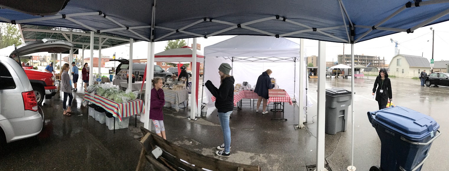
Wow, what a month February was. It’s been a little over a month since we kicked off the 2020 CSA season and our CSA slots are almost full. A huge thank you is in order for everyone who’s supporting us by ordering.
If your considering a CSA order, we have a couple slots open so let us know what you want.
Thanks again for getting 2020 off to a great start.
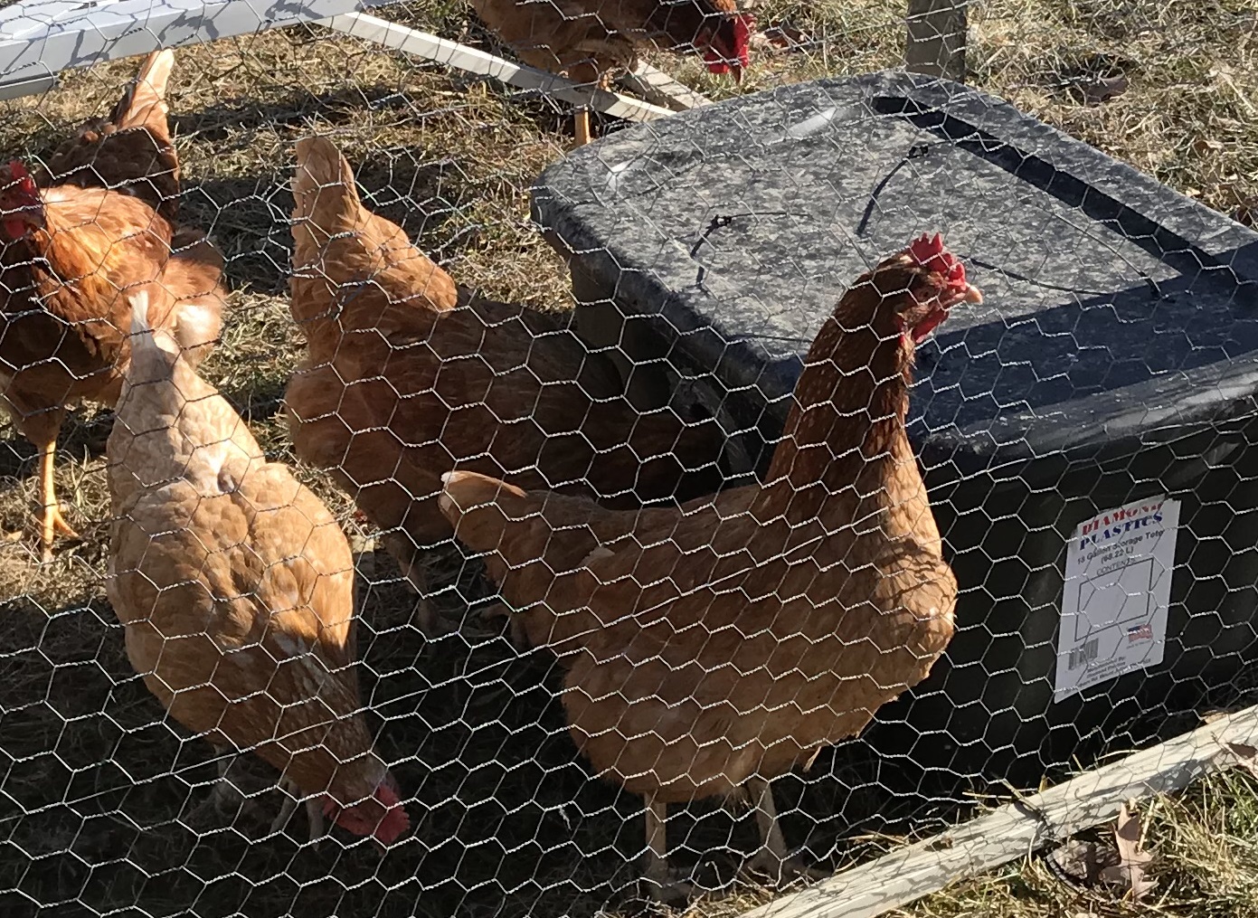
Providing unfrozen water in the winter can be a challenge and time consuming. Since we pasture the chickens “tractor” style with the portable coop, power to heat the water is the issue. I believe I’ve finally figured it out.
First year we started with multiple plastic waterers that we swapped out multiple times a day. This works decently, but the water still freezes, it’s labor intensive, and someone needs to be around during the day to swap waterers.
The next year we steped it up by heating the waterers with a light bulb. This worked pretty good, but required us to keep the coop within extension cord distance of an outlet and periodically water would freeze in the top of the waterer.
I did not do a post on the tire waterer. It was disappointing and it was easy to find info on it. However, I still had the tire and pan laying around so I threw together a quick pic for reference.
Last year I built a tire waterer to try and keep the chicken water from freezing. I put a board inside the tire on the bottom side, stuffed the inside of the tire with old tarps for insulation, and fitted a plastic pan in the tire. My experience with that was poor and I do not recommend it. The biggest issue was that the chickens would stand on the tire and mess in their water all day. By the time I got home to change it, it was pretty bad. It did help slow down the freezing process; however, being open air, it still allowed the water to eventually freeze solid, especially overnight.
I’ve been playing with an idea of an enclosed PVC and nipple system. Basically building an insulated box and filling it with 3″ tubes of PVC, shown in the graphic. There would be a cutout of frame and insulation in one top corner to allow access to add water. One bottom corner would have a smaller PVC tube that protruded through the box with a water nipple on the end. The front would be Twinwall Polycarbonate glazing to let the sun in and the inside would be painted black to absorb as much heat as possible.
It was getting cold this year and I needed to get a waterer made for the chickens so I decided to not build the PVC waterer for the following reason. One, my chickens are not trained to a nipple system yet. I’m having trouble figuring out how to attach the PVC box to the ‘Pequod’ chicken coop, especially since it’s going to be heavy and need decent support. The 3″ PVC fittings are expensive and I have concerns the metal part of the nipple would still freeze and cause issue.
I was basing the PVC system on principals I learned from this solar horse tank. Then it hit me, how about trying to replicate the horse tank at a chicken waterer size! Since the amount of water would be significantly less, I wouldn’t want to leave the top exposed, but chicken heads are small, so I took a gamble that they’d stick their heads through a hole instead.
My first thoughts were to use a bucket, but I didn’t like the clearances nor dealing with bending and attaching the polycarbonate glazing. So I decided to use a tote, black obviously so it will absorb the heat from the sun.
Using similar principals as the solar horse tank. I first put 2″ foam on the bottom to have an insulated base to sit the water on. I measured from the top of the foam to the bottom of the lid and subtracted 2 inches for the foam that would be attached to the lid. This gave me the height for the foam sides and Twinwall Polycarbonat glazing
Next I added the 2″ foam to the sides. I looked at the shape of the tote and measured across the end where I could fit a straight piece of foam. The bottom of the tote is narrower than the top, measured top and bottom and cut sloped pieces of foam.
I measured from the floor to top and between the insides of the sides to cut a rectangle out of the front of the tote for the window. I cut a piece of polycarbonate glazing slightly larger, about 1/2 to 3/4 inch, than the hole on the sides and bottom so that the foam could help hold it in place. I used duct to hold and seal the polycarbonate glazing in place; this also sealed the tubes. I put the scrap piece of plastic from the side on the floor in front of the window to try and suck in more heat.
On the other side, I placed the water bowl in the tote and used the top of the bowl to mark the bottom of the drinking opening. Using a hole saw, I cut two overlapping circles to make the oval shaped opening for the chickens to sick their head in to drink, cleaning up the oval edges with a utility knife.
I thought it would be better to use a thinner foam where the hens stick their heads in, so I cut a piece of 1/2 inch foam, from scrap I had, to cover this side, removing the same oval. I used duct tape to hold the foam pieces together and seal the seams. I also used several pieces of duct tape to secure the foam to the hole and prevent the chickens from rubbing the foam.
Next I cut the 2″ foam for the lid making it fit snug when placed in the tote, but not too snug as it’ll need to be opened and shut frequently. With the foam in the tote and the lid on, I drilled 4 sets of 2 holes so I could use zip ties to secure the foam to the lid. I also cut some small squares of plastic from something in the recycling to prevent the zip ties from digging into the foam and pulling through.
From the drinking hole, I wanted to minimize the surface area of the incoming air over the bowl. I used 2″ foam to make a bridge over the bowl, then added 1/2 foam on either side of the hole to create a smaller cavity where the outside air had direct contact with the water.
At this point I put the waterer into action; however, I forgot chicken peck. I’m not sure why I thought they wouldn’t peck the foam bridge, but I did and they did, effectively destroying the bridge.
So… I redid the bridge. I used corrugated plastic from an old ‘For Sale’ sign I had on all the pecking sides of the bridge and plenty of duct tape to hold it in place. The 2″ foam was replace with 1/2″ foam over the bowl. I didn’t account for needing to remove the bowl to clean it and the 2″ foam made it so I had to tip the bowl to get it out. Now I don’t have to.
How well does it work? Great. Basically, overnight at 15-19 degrees Fahrenheit I had about 1/8 inch of ice frozen on the top of the bowl. Down in the teens is a bit thicker. In the morning if the bowl was full of water, pull the bowl out and bang it upside down on the ground to remove the ice. If it’s half or less, then fill it with warm water from the tap and melt the ice that way.
During the day, in the teens and twenties the water stays unfrozen, especially if there is sun, but even on overcast days, there should be enough solar to keep it unfrozen. Unfortunately, we only had a few days this winter where it stayed below freezing night and day for 2 or more days, so I cannot give accurate results for long cold spells; however, given what I’ve seen so far it should work great. The heat from the warm water in the morning in conjunction with the passive solar heat should keep the water from refreezing during the day.
With all my scraps, this was a pretty cheap build and worth every penny. $6 for the tote and $10 for the rubber bowl, and $20 for the polycarbonate glazing. (the link isn’t the one I purchased, but this is a similar 5 pack) I had 2″ and 1/2″ foam left over from insulating the basement and other projects.
Our off-season hiatus is over and the 2020 season is officially kicking off. We’ve been reviewing, planning, and scheduling so we could get the 2020 info out to you.
We’re now taking orders for our CSA. Please consider ordering a CSA to get our best pricing and guarantee your spot in line for chicken in case we sell out early again.
Your support through our CSA support it is the heart of our operation. Without it, we wouldn’t be able to provide produce our quality chicken for you.
This year we have to increase our prices for the first time. To help compensate, you’ll notice we’ve increased the CSA discounts. It makes even more sense than ever to purchase a CSA.
Check out our CSA Page for full details and to order.
Brothers M. Mondays in May is back – A new post each Monday in May 2019.
Taking care of the chickens can be fun and entertaining, but it’s still a lot of work.
The bulk of the work is in the daily feeding, watering, and moving of the chickens. Multiple daily trips to the pasture are required to properly care for the birds. We take pride in the care we give to raise quality chicken, even when it’s raining.
Besides the daily care, there are several other days that require extra amounts of labor. Over 200 chickens are handled once when we receive them. Handled two times when moving from the brooder to pasture and three times during processing. There are also maintenance days such as working on the chicken tractors and cleaning the brooders and equipment.
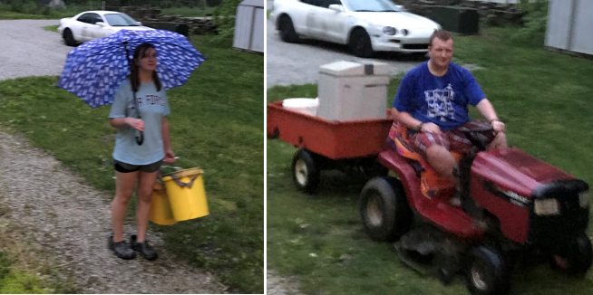
But, my favorite are the days we get the feed. Helping the kids lug around 50lb bags of feed makes a person feel good.
Usually we load a lawn trailer to carry the bags down the hill. This year we had mechanical issues half way through so Matthew got to strut his stuff by doubling up.
Brothers M. Mondays in May is back – A new post each Monday in May 2019.
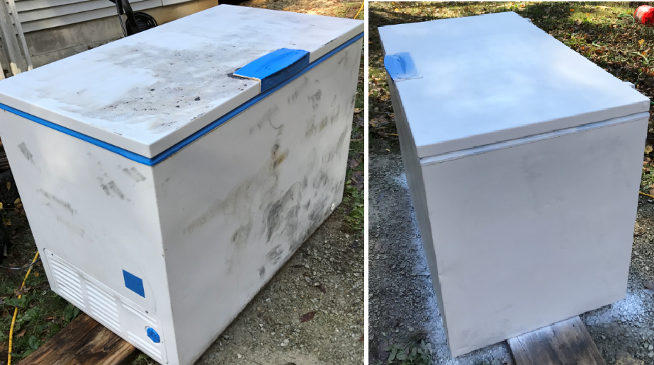
One of our big investments for raising chickens is the freezer space and the space the freezers take up. We have one porch freezer and it picked up a lot of rust over the last couple years. I figured I’d wire wheel it down and repaint it to try and keep it around longer. Here’s some of the pictures of the process.
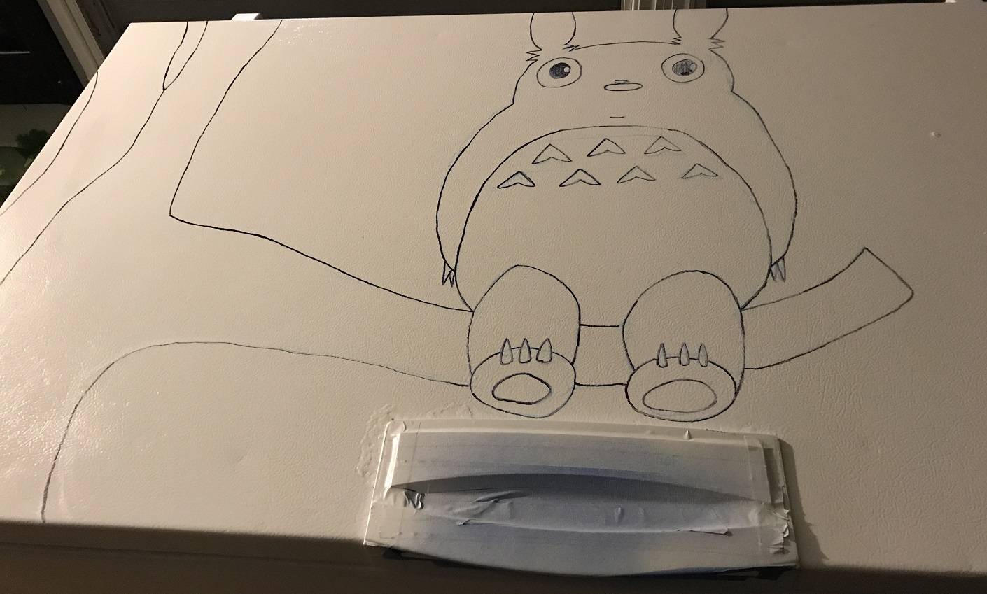
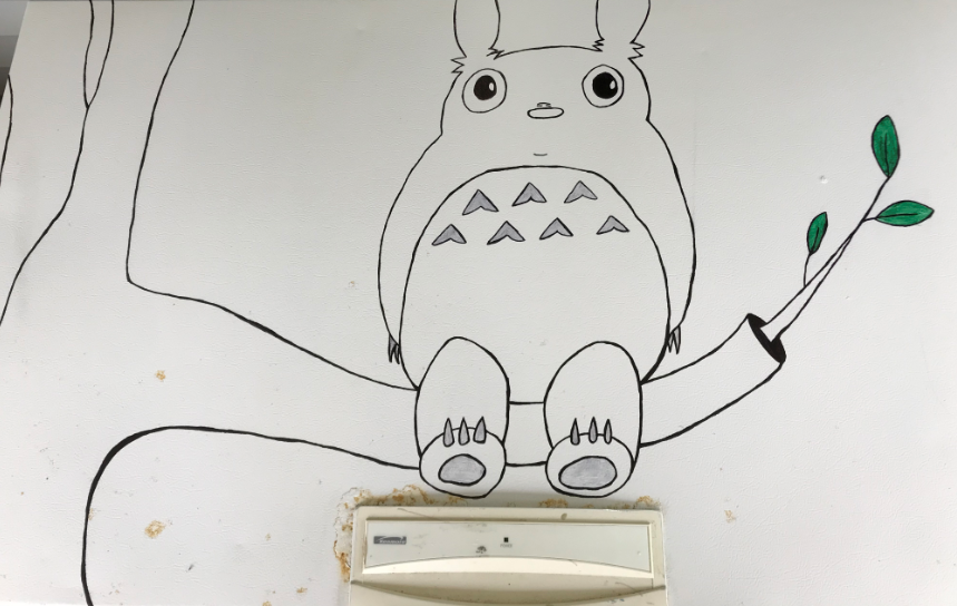
After I painted it, Samantha added her special touch to the lid. She originally didn’t want to add any color to it, but the family kept at her and this spring she added some color. Unfortunately, you can see some of the rust coming back, but it’s still lots better than it was. And I love the Totoro!
Electronics were a must for me. Probably the best thing I liked about keeping the birds in the chicken tractor was not having to open and shut a coop door each day. Therefore an automated coop door was a requirement for this build.
When I started the electronics, it became a “give a mouse a cookie” event. Automated door meant battery, battery meant solar panel, and since we have a solar panel, let’s do lights. And for grins, I’m toying with adding a winch to raise and lower the aviary, so let’s add something for that.
I already had the battery, lights, and timer from the A-Frame build. However I wanted to add solar to charge the battery instead of manually charging it 1-2 times a week. I looked at some kits online and chose a cheep 20W panel and charger off Amazon. The door automation took more thought.
I looked online and saw people using car antenna motors to open and shut the door. I like this idea. It would limited the amount of push pressure when shutting the door, which would prevent birds from getting caught, but this could also end up leaving the door open if the door got in a slight bind. The biggest con for me not to use this was that, for my build, constant power would need to be applied when the antenna was extended, which would be during the nighttime when the door was pushed closed. This would cause a draw on the battery; however, it would be a slight draw because it’s not running the motor.
Liner actuators are the other main way I see coop doors automated. These are on when moving, then switch off once extended or retracted. To reverse the direction, you reverse the polarity. So they only draw power twice a day when opening or closing. They also have a lot more push/pull torque. This would prevent the door staying open at night because of a slight bind in the door; however, poses a danger if a chicken is in the way. I was leaning toward the linear actuator when once again my father-in-law helped out and gave me one he had.
The actuator requires a DPDT relay to reverse the polarity. In the end, the power draw from the power antenna was probably a wash with the relay draw; however, the way I architected my door, the relay draws power during the day and the antenna would be drawing at night. Theoretically there should be less draw on the battery as the solar panel will power the relay during the day. Again, the draw is slight and probably not worth worrying about, but I do.
I’ll still have a constant phantom power draw from the photocell (circled in red in the picture of the solar panel) that’s used to trigger the door at morning and night, but that’s used for either method. I like the photocell because it changes with the season and will be more consistent with morning and night than trying to use a timer.
I spent some time to determine the correct wire for the distance. Based on this chart, the battery distance of 12′ with 5A puts me at 12 gauge. I decided to use 12 AWG to the battery and 16 AWG to everything else to achieve a 2% voltage loss. I save old appliance cords that are long, like from vacuum cleaners, and used these for the rest of the connections. They are 16/17 gauge and should keep me in the 2% drop range based on a combination between the previous chart and this chart. As with the power draw of the antenna, I may be over thinking/engineering this for a chicken coop.
Finally, I had picked up an old electrical panel box somewhere and I used it to house all brains of the electronics. I added a board to help me mount everything in the box. Here’s how it fits together.
Battery
First I bring the battery wires into the box to a couple of terminals. This allows me to connect things directly to the battery and bypass the solar charger, which is rated for 3A. My first add-on is a cigarette lighter that I mounted in the bottom of the box.
Solar
Then I attached the solar charge controller to the battery terminals. The Solar panel connects into the charge controller. Finally I take the load from the charge controller to two more terminals that I’ll connect everything else to. Connecting solar is pretty simple using a charge controller, especially compared to the wiring for the lights and door.
Lights
As I mentioned in my previous post on the lights, I need a relay for the timer to power the lights. I could not power my light directly through the light switch. I also used 3 wires going to the light so I could add a flip switch to override the timer and turn the lights on. These two items make the wire diagram look like spaghetti, but hopefully you can follow it.
**If you’re comparing the diagram to the photograph, the diagram has positive in red and negative in black. That does not correspond to the wires I actually used so I list the color of the wire in the photograph in (parentheses).
Power(positive) comes from the load terminal to the switch side of the timer, a jumper wire goes to a wire nut that ties to the run side of the timer, which also jumpers with the power(black) wire to the light, and the switch side of the relay. All these connections have power full time. The other side of the relay switch goes to the switched wire(green) to the light. And the other switch side of the timer connects to the coil side of the relay.
Negative goes from the load terminal to the relay coil and run side of the timer, where it’s jumpered with the negative(white) wire to the light. This provides the 3 wires going to the light as Black=always on positive, Green=switched power from the timer, white=negative(common). Because I’m using wire commonly used for AC, I switched to AC Black/white color standards when I attached the wire or when I ran out of Red/black wire. It makes sense to me since I’ve dealt with both.
At the light switch, negative(white) goes straight to the light. Positive(Black) goes to one side of the switch. Switched(green) goes to the other side along with a jumper wire to the positive side of the light. So if the light switch is on, it provides power to the green side that’s jumpered to the light and the light comes on. Turned off and the light is off, UNLESS the time is on and sending power through the Green wire, which in turn will power the light.
Door
Hooking up the DPDT relay to switch the polarity for the actuator is fairly simple if you look at it in my diagram. You have two COM posts that you hook positive and negative to. Each one of those two posts will connect to 2 more post, one if the relay coil has power (SNO), the other if it doesn’t (SNC). To reverse the polarity connect the 4 posts in a crisscross pattern. The wire going to the actuator will connected to the 2nd pair. If the direction of the actuator is wrong, just revers the actuator connection.
To connect the coil side of the relay you add in the photo cell so you are providing power to the coil in the day time and not at night. You need 3 wires going to the photocell, power(black) and Negative(white) connect to the load termnals and switched(Green) will return from the photocell and connect to the coil.
To reduce the number of wires coming from the load terminals I jumpered the negative wire with the COIL and COM terminals on the relay and the (white) wire to the photocell. I jumpered the positive wire between the COM on the relay and the (black) wire going to the photocell.
** To really confuse things, I accidentally jumpered in an extra (blue) wire with the positive connections. I didn’t need, but didn’t want to re-do the connection so I just capped it off (white cap_.
Actuator and door
Due to the window, I wanted my door to slide sideways open and shut. I had 2 keyboard tray slide rails which would worked perfect. They allow the door to slide 1.5 inches. The actuator moves 10.55 inches, so I just needed to add a little play in the connections and all is good.
I started with framing where the door would slide. I framed is so the actuator and most of the rails could be enclosed with a piece of OSB (red outline with arrow pointing to the OSB) to prevent dirt and droppings from getting on them since the perch was close by. I cut a door that’s wide enough to cover the door opening and slide behind a piece of wood that will prevent the rails from being bent back allowing a predator to squeeze through the door. I attached the door and rails.
Here’s a video of the door opening and me demonstrating how to manually shut the door.
I cover my initial build of the boxes, including covering the paint trays, for the A-frame here. As I mention, I really like this type of box. And to follow-up from my first post, yes the new ISA Brown flock is consistently laying only in the boxes as I had hoped and expected.
The boxes for this coop are completely on the outside of the coop. This gives me more room on the inside of the coop for roosting and waste/droppings management. I put the boxes level with the floor. I’m getting bedding shavings in the trays, which can prevent eggs from rolling down. I’m not sure if higher tray would fix the issue, but I’m planning to move to a mesh floor without any shaving anyway, so the issue should resolve itself with the new floor.
The dimension of the boxes are mainly to accommodate the paint trays, but I think are good for any box. I typically do not oversize my boxes, especially in height. I’ve read that keeping the boxes smaller and shorter discourages “parties” in the boxes that lead to droppings in the box. So far that’s not been an issue in any of my boxes. Additionally I use an old table cloth to make a divider to give the hens more privacy, which they really seem to like.
I started by marking the ends according to the blueprints, putting each board on the marks to ensure I had the right dimensions, then cutting out the end shape. I then cut all the horizontal boards to the proper length. I used standard 1″ & 2″ sizes and laid out the paint tray on the boards to ensure proper dimensions before I cut them. The larger floor and roof I used scrap OSB and a an old shelf board I had on hand.
I took the roof angles from the ends used them to ripped an angle on the 3 boards that meet the roofs. I could have just left them square and lowered them to the level of the roof, but I like the way the angle looks.
Then I sat the ends upright and started fastening the horizontal boards to the ends. I have a staple gun which makes building boxes like this much easier. It could probably be done without it, but I’ve come to rely on how well the staples work in edges of narrower pieces of wood.
I slid the paint trays in to view the heights. The 1×6 that I used for the back of the nesting box did not go down as far as I liked. It gave the chickens too much room to access the bottom of the pan. I ripped a spare board in half and used it to add to both boxes.
I cut and stapled the center in place. I have a staple gun which makes building boxes like this much easier. It could probably be done without it, but I’ve come to rely on how well the staples work in edges of narrower pieces of wood. I also ripped the appropriate angle on the board that covers the egg area so it sits flush on the hinge side, but did not attach it yet.
Next I fastened the boxes to the frame using carriage bolts in the top to hold the weight then wood screws at the bottom to hold the box against the frame. The frame had a lip that was perfect to rest the box on and use a clam to hold it in place while I fastened it.
Finally, I attached the roof sections. The top one I just stapled down, the bottom one is hinged so t raises for gathering eggs. Since I used OSB, the top roof has tar paper for now and will get a either shingles or a metal roof. The bottom roof/door is a 1×8 and will just get stained.
Several years ago, I said this build has been on my mind for a while, I decided a coop on a trailer should be low to the ground. Honestly don’t remember why I thought this at the time, but I shared the idea I had for making tires shorter with my father-in-law. He wasn’t so much interested in the lower trailer, but was very interested in tires that won’t go flat.
So the trailer’s tires he gifted me had been modified for about 2 years. I give thanks again to my father-in-law not only for all the parts he donated to this project, but for making my job easier. He already cut the sidewalls off the tires, shortened the remaining tread, and bolted the ends to the rim. In addition to all this work, the passing of time and trailer use identified a couple areas that needed improvements.
Initially he only bolted the cut tires to the rim in one spot, where the rubber ends met. A miscalculated in the circumference resulted in the tread being cut too short, hence the extra ad-on pieces you’ll see in the pictures. The rubber was stretched tight and the edges curved around the rim, so it seemed like the rubber would not drift. In this picture you see it did drift off the rim. I added 2 additional fastening points approximately every 120 degrees.
Second, where it was bolted wood pieces were used as spacers. These rotted and fell apart. I decided to used foaming insulation instead and becasue I was adding additional bolts, I did it completely around the wheel.
Lastly, the rotted wood pointed out that the cupped rubber on the wheel was holding water. Standing water is not good for the metal rim to sit in. This I haven’t mitigated yet, but the plan is to cut some holes in the rubber to allow for drainage, and have awnings over the tiers so they don’t get as much rain to begin with. I overhung the roof in the back to do this, and in the front, I’ll add an awning that will double as an extension for water nipple.
Roof
I wanted the roof to overhang in the front and back. The backside covers the wheel and the nesting boxes. I added a gutter for additional overhang to divert the rain away from the nesting boxes and for potential for rain catchment later. As you can see in the picture, the additional length comes in handy in the winter.
The front overhang is to shade the windows in the summer, when the sun is high overhead. During the cooler/cold seasons when the sun is lower in the sky, it will still shine into the coop for additional passive solar heat. The overhang also helps with the pulleys for the aviary and to keep the rain off the windows and wheel.
I added a layer of foam board under the roof for insulation. I’m not concerned with sealing the coop tight, but I wanted more than a thin roof between the hot sun in the summer and cold in the winter.
Due to timing and budget, I started out with some used scrap roofing I picked up fee for projects. What I had left was in pretty bad shape and I only intended it to make it through the winter before I replace it with a metal roof. It didn’t.
Fortunately the high winds that blew off the first roof were from a warm front. This at least providing me with a some above freezing temperatures as I replaced it with a metal roof. I was going to special order a blue metal roof to coordinate with the blue frame, but when you need it today, you take what’s in stock at the hardware store.
Color
The final basic item for the build is the color. Everything I’ve built since we move out here has been grey with green roof and trim. This matches the house. But as I mentioned, the trailer frame was previously blue and nearly screamed at me to be blue again. Additionally, I didn’t have any grey stain on hand and had already spent more than my budget for the first phase of this project.
As I was fretting over the color change, I happened to watch this double-decker bus conversion video and at 12:10 the interviewer says “It’s green!” and the builder’s reply was “It was going to be blue, but now it’s green”, basically because he’s made due. I have white stain and white and blue go great together, so it was going to be grey, but now it’ll be white.
Additionally a white coop makes me think of it as a symbol of Captain Ahab’s white whale. In the last several years, chickens have certainly been my “white whale”. I’ve also nicknamed the coop the Pequod. Not sure it’s going to stick, but I tried.
Finally, It goes against my upbringing to build without properly protecting the wood with stain, but I was limited by time and warm weather. I settled for staining the trim and pieces that were going to overlap, so I wouldn’t have to take them apart later. Hence why I went with white and why you see some white stripes on the ends.